4.5 - Manifold Gauge Set and Service Hoses
Module: Refrigeration Cycle Components Gauges and Pressure-Temperature Relationships
Course role: Explains the parts, flow paths, service connections, hose practices, and refrigerant-release controls associated with a typical refrigeration manifold gauge set
Learning Objectives
After completing this section, a student should be able to:
- Identify the compound gauge, high-pressure gauge, manifold valves, side ports, and center service port on a typical manifold gauge set.
- Explain what the low-side and high-side gauges measure and identify an important limitation of the compound gauge during deep evacuation.
- Explain how the manifold valves control communication between the low-side, high-side, and center service connections.
- Select the appropriate center-hose connection for pressure measurement, refrigerant charging, recovery, and evacuation.
- Explain how low-loss fittings, correct hose handling, and air-removal procedures reduce refrigerant emissions and system contamination.
- Describe safe, technically appropriate connection and disconnection practices without relying only on hose color or assuming that every manifold has the same internal design.
Introduction
A manifold gauge set is one of the most familiar service tools in refrigeration and air-conditioning work.
A traditional two-valve manifold combines:
- A low-side or compound gauge.
- A high-pressure gauge.
- A manifold body.
- A low-side valve.
- A high-side valve.
- A low-side service hose.
- A high-side service hose.
- A center service hose.
The manifold allows a technician to connect the refrigeration system to instruments or service equipment while controlling the flow path.
Typical uses include:
- Measuring low-side pressure.
- Measuring high-side pressure.
- Connecting a refrigerant source.
- Connecting a recovery machine.
- Connecting a vacuum pump.
- Performing selected charging or service procedures.
A simplified arrangement is:
Low-side service port
        │
        │ Low-side hose
        ▼
Compound gauge
        │
   Low-side valve
        │
        ├──────── Center service port
        │
   High-side valve
        │
High-pressure gauge
        ▲
        │ High-side hose
        │
High-side service port
The center service port is commonly connected to one service device at a time, such as:
Refrigerant source
or
Recovery machine
or
Vacuum pump
A manifold gauge set is not simply a pair of pressure gauges.
The technician must understand:
- Which port is connected to which pressure region.
- What the manifold valves actually open or close.
- Whether air is trapped in a hose.
- Whether refrigerant can be released during connection or disconnection.
- Whether the hose and manifold pressure ratings are suitable.
- Whether the refrigerant and lubricant can contaminate another system.
Connecting or disconnecting service hoses is a refrigerant-handling activity. Good technique therefore matters for both technical accuracy and refrigerant conservation.
Key Concepts
1. Typical Three-Hose Arrangement
A traditional manifold often uses three service hoses.
| Hose Function | Typical Connection | Common Color Convention |
|---|---|---|
| Low-side hose | Low-side / suction access point | Blue |
| High-side hose | High-side access point | Red |
| Center service hose | Refrigerant source, recovery machine, or vacuum pump | Yellow |
The colors are a common industry convention.
They are not a substitute for:
- Reading labels.
- Tracing the hose.
- Identifying the manifold port.
- Confirming the system access point.
A technician should never connect a hose solely because of its color.
2. Gauges and Valves Perform Different Functions
The gauges measure pressure.
The manifold valves control flow paths.
On a typical two-valve manifold:
- Closing the low-side valve normally blocks communication between the low-side hose and the center port.
- Closing the high-side valve normally blocks communication between the high-side hose and the center port.
- The gauges can still read the pressure at their connected side ports even when the corresponding manifold valve is closed.
This is a high-priority concept.
On a typical manifold, a valve does not have to be opened merely to read the pressure already connected to that gauge.
Manifold designs vary. Digital manifolds, four-valve manifolds, and specialized evacuation manifolds can use different internal passages.
Always understand the specific manifold’s flow diagram.
The Compound Gauge
1. Purpose
The low-side gauge on a traditional manifold is usually a compound gauge.
It is called compound because it can indicate:
- Positive gauge pressure above atmospheric pressure.
- Vacuum below atmospheric pressure.
A simplified scale can include:
Vacuum region
← 0 psig → Positive low-side pressure
2. Typical Use
The compound gauge is connected through the low-side hose to a low-side access point, commonly in the suction region.
It is used to observe:
- Low-side operating pressure.
- Suction pressure.
- Pressure during selected recovery procedures.
- Rough vacuum indication during evacuation.
3. Vacuum Scale
A traditional compound gauge commonly displays vacuum in:
inches of mercury vacuum
This indicates pressure below atmospheric pressure.
The exact relationship among:
- psig.
- psia.
- inches of mercury vacuum.
- millimeters of mercury absolute.
- microns.
is developed in Section 4.6 - Gauge Pressure Absolute Pressure and Vacuum.
4. Compound Gauge Is Not a Deep-Vacuum Instrument
A mechanical compound gauge is useful for showing that pressure has fallen below atmospheric pressure.
It is not sufficiently precise for verifying a deep evacuation.
For deep evacuation:
Use an appropriate micron gauge.
The compound gauge should not be used to claim that a system has reached a deep-vacuum target such as several hundred microns.
This distinction prevents a common service error:
Compound gauge shows near 30 in. Hg vacuum
≠
verified deep vacuum
The High-Pressure Gauge
1. Purpose
The high-pressure gauge measures pressure on the high side of the system.
It is commonly connected to:
- A discharge-side access point.
- A liquid-side access point.
- Another manufacturer-provided high-side service connection.
The location matters because pressure drop can exist through components and piping.
2. Typical Reading
During normal cooling operation, the high-pressure gauge generally indicates a positive pressure substantially above the low-side pressure.
The actual value depends on:
- Refrigerant.
- Condensing temperature.
- Ambient or cooling-water condition.
- Load.
- Airflow or water flow.
- System design.
Therefore, one pressure number is not normal for every system.
3. Pressure Range and Tool Rating
The manifold and hoses must be suitable for the pressures expected with the refrigerant and system.
Before connecting:
- Check gauge pressure range.
- Check manifold pressure rating.
- Check hose working-pressure rating.
- Check fitting compatibility.
- Inspect hoses for damage.
A manifold intended for a lower-pressure refrigerant may not be suitable for a higher-pressure refrigerant.
Do not use a tool merely because the threaded connection can be made.
Manifold Body and Valves
1. Typical Two-Valve Manifold
A traditional manifold has:
- Low-side port.
- High-side port.
- Center service port.
- Low-side valve.
- High-side valve.
A conceptual internal arrangement is:
Low-side gauge / hose
        │
        ├── Low valve ──┐
        │               │
        │          Center port
        │               │
        ├── High valve ─┘
        │
High-side gauge / hose
The exact passage design depends on the manifold.
2. Both Valves Closed
For a typical two-valve manifold:
Low valve CLOSED
High valve CLOSED
means the center service port is isolated from both side hoses.
However:
- The low gauge can still see low-side pressure through the low hose.
- The high gauge can still see high-side pressure through the high hose.
Therefore, both system pressures can normally be observed with both manifold valves closed.
3. Low-Side Valve Open
Opening the low-side valve connects:
Low-side hose
↔
Center service port
This can be used, depending on the service procedure, for:
- Charging through the low side.
- Recovering from the low side.
- Evacuating through the low side.
4. High-Side Valve Open
Opening the high-side valve connects:
High-side hose
↔
Center service port
This can be used, depending on the procedure, for:
- Recovery.
- Evacuation.
- Selected charging procedures when the equipment and operating condition permit.
5. Both Valves Open
If both manifold valves are opened:
Low side
↔
Center port
↔
High side
Both sides communicate through the manifold.
This may be intentional during:
- Evacuation.
- Some recovery arrangements.
It can be inappropriate or dangerous during other operating conditions.
Do not casually open both valves on an operating system.
6. Valve Position Must Match the Task
Before moving a manifold valve, ask:
What is connected to the center hose?
Where will refrigerant flow if this valve opens?
Is the system running or off?
Is the intended path safe and approved?
This habit prevents many service mistakes.
Center Service Hose
1. Center Port Is the Service Connection
The center manifold port is commonly the connection used for an external service device.
Depending on the task, it can connect to:
- Refrigerant cylinder or charging source.
- Recovery machine.
- Vacuum pump.
The center hose is commonly yellow, but color is not the technical definition.
2. One Port Can Serve Different Functions
The center port does not permanently belong to only one device.
Its function changes with the service operation.
| Service Operation | Typical Center-Hose Connection |
|---|---|
| Pressure measurement only | Center hose isolated or capped |
| Refrigerant charging | Refrigerant source |
| Recovery | Recovery-machine inlet in a common manifold arrangement |
| Evacuation | Vacuum pump |
The technician must confirm the manifold and equipment arrangement before opening valves.
Pressure Measurement Connection
1. Typical Connection
For simultaneous system pressure measurement:
Low-side hose
→ low-side access point

High-side hose
→ high-side access point

Center service port
→ isolated / capped
The manifold valves normally remain closed.
2. Read Before Opening Valves
With the side hoses connected and the manifold valves closed, the gauges on a typical manifold can read the pressure at their corresponding access points.
Opening a valve is not required simply to obtain the gauge reading.
This reduces unnecessary refrigerant movement.
3. Know the Access-Point Location
A low-side gauge reading represents the pressure at the actual low-side connection.
A high-side gauge reading represents the pressure at the actual high-side connection.
Do not assume:
- Every low-side access port is at the same exact location.
- Every high-side access port is directly at compressor discharge.
- Every appliance has both permanent access ports.
Access-point differences were introduced in Section 4.3 - High Side Low Side and Refrigerant Lines.
Refrigerant-Source Connection
1. Typical Arrangement
For a charging operation, a common arrangement is:
Refrigerant source
→ center hose
→ manifold
→ selected system side
The exact charging path depends on:
- Refrigerant.
- System design.
- Equipment operating condition.
- Manufacturer procedure.
- Whether liquid or vapor is required.
- Whether the system is operating.
2. Do Not Generalize One Charging Route
A manifold can physically route refrigerant to either side, but that does not mean every route is appropriate.
For example:
- Zeotropic blends are normally withdrawn from the supply cylinder as liquid to preserve composition.
- Liquid refrigerant must not be allowed to slug a running compressor.
- Some charging procedures require the system to be off.
- Some systems specify charging by measured mass.
- Manufacturer procedures control the correct final charging method.
Detailed superheat/subcooling interpretation is covered in Section 4.8.
3. Air in Charging Hoses Is Contamination
Before refrigerant is introduced through a hose, air should not be left trapped where it will be pushed into the sealed refrigeration system.
Air can become a noncondensable contaminant and can:
- Raise head pressure.
- Reduce condenser effectiveness.
- Introduce moisture.
- Interfere with system operation.
Therefore, service hoses must be prepared by an approved procedure that removes air while minimizing refrigerant release.
Recovery-Machine Connection
1. Common Manifold Arrangement
A basic training arrangement can use:
Appliance low/high access
→ manifold side hoses
→ center hose
→ recovery-machine inlet
→ recovery machine
→ recovery cylinder
This allows the manifold valves to control which appliance side communicates with the recovery machine.
2. Follow the Recovery-Machine Flow Direction
A recovery machine has an intended:
- Inlet.
- Outlet.
The refrigerant path must follow the manufacturer’s instructions.
A common conceptual path is:
Appliance
→ Recovery-machine inlet
→ Recovery machine
→ Recovery-machine outlet
→ Recovery cylinder
Do not reverse the machine connections.
3. Manifold Is Not Always the Fastest Recovery Path
A manifold and small-diameter hoses can add flow restriction.
For some recovery procedures, the equipment manufacturer may recommend:
- Direct hose connections.
- Larger hoses.
- Valve-core removal tools.
- Liquid recovery from an appropriate access point.
Therefore:
The manifold arrangement is a useful teaching model, not a universal requirement for every recovery procedure.
Later recovery modules develop equipment-specific recovery arrangements in greater detail.
Vacuum-Pump Connection
1. Typical Manifold Arrangement
A basic evacuation connection can be shown as:
Low-side access
        │
        ▼
     Manifold
        │
        ▼
Center hose
        │
        ▼
Vacuum pump
With both low-side and high-side hoses connected, opening both manifold valves can provide evacuation paths from both sides of the system.
2. Air and Water Vapor Must Be Removed
Evacuation is used to remove:
- Air.
- Other noncondensable gases.
- Water vapor.
The vacuum pump is not a refrigerant recovery device.
Before evacuation of a charged system:
Refrigerant must first be recovered as required.
3. Deep Evacuation Requires Proper Vacuum Tools
A conventional manifold set can be used for some evacuation tasks, but it can also add restriction.
Efficient deep evacuation may use:
- Large-diameter vacuum-rated hoses.
- Short hose paths.
- Valve-core removal tools.
- A vacuum pump with clean oil.
- A micron gauge located to represent system vacuum rather than pump inlet vacuum.
The detailed vacuum-pressure units are covered in Section 4.6.
4. Compound Gauge Does Not Verify Microns
The manifold’s compound gauge is not a substitute for a micron gauge.
Correct distinction:
Compound gauge
→ operating low-side pressure
→ rough vacuum indication

Micron gauge
→ deep-vacuum measurement
Low-Loss Fittings
1. Purpose
A low-loss fitting is designed to close automatically, or to be closed manually, when disconnected so that refrigerant release from:
- Hoses.
- Appliances.
- Recovery or recycling equipment.
is minimized.
Typical examples include:
- Self-sealing hose-end fittings.
- Manual shutoff fittings.
- Ball-valve hose ends.
- Other approved low-loss connection designs.
2. Why Low-Loss Fittings Matter
A service hose can contain refrigerant under pressure.
Without a low-loss method, disconnecting the hose can release:
- Refrigerant trapped in the hose.
- Refrigerant from the appliance access fitting.
- Refrigerant from recovery equipment.
Low-loss fittings reduce this release.
3. Current Recovery-Equipment Requirement
Current federal recovery/recycling-equipment standards require covered certified recovery and recycling equipment to have low-loss fittings on all hoses.
The broader technician principle is:
Use connections and procedures that minimize refrigerant loss.
4. Low-Loss Does Not Mean Zero-Loss
A low-loss fitting reduces refrigerant release.
It does not guarantee:
zero refrigerant release
Small incidental releases can still occur during hose connection or disconnection.
Current federal rules recognize limited de minimis releases associated with good-faith refrigerant recovery or service, including incidental releases during hose connection and disconnection.
This is not a general permission to vent refrigerant.
Purging or Clearing Service Hoses
1. Why Air Must Be Removed
When a hose is open to the atmosphere, it contains:
- Air.
- Water vapor.
If the hose is connected to a sealed refrigeration system and the trapped gas is pushed into the system, contamination is introduced.
Therefore:
Air must be removed from service hoses before the hose contents are introduced into the system.
2. Purging Does Not Mean Routine Venting
The word purge is sometimes used loosely in service discussions.
Do not interpret it as permission to discharge refrigerant deliberately to the atmosphere.
The preferred principle is:
Remove air from hose
+
minimize refrigerant release
+
follow approved equipment procedure
Depending on the equipment and task, this can involve:
- Evacuating the hose or manifold assembly.
- Using an equipment-designed closed purge procedure.
- Routing displaced gas into recovery equipment.
- Using low-loss fittings and shutoff valves to minimize trapped volume.
3. Incidental Connection Loss Versus Intentional Venting
A very small refrigerant release that occurs incidentally while connecting or disconnecting hoses during good-faith service is different from deliberately venting refrigerant as a routine practice.
Therefore:
Minimize unavoidable connection loss
≠
intentionally vent hose contents
4. Recovery Hoses Also Need Air Control
Air left in a recovery hose can contaminate recovered refrigerant and increase noncondensables in the recovery cylinder.
Before recovery:
- Use the recovery-machine procedure for clearing or evacuating hoses.
- Confirm the recovery cylinder and hoses are appropriate.
- Avoid introducing air into the recovered refrigerant stream.
Minimizing Refrigerant Releases
1. Plan the Connection Before Opening the System
Before attaching hoses:
- Identify the refrigerant.
- Identify the low-side and high-side access points.
- Inspect the manifold.
- Inspect hose seals.
- Confirm pressure ratings.
- Position valves correctly.
- Determine what will be connected to the center hose.
- Prepare the recovery cylinder, vacuum pump, or refrigerant source before opening valves.
Planning reduces unnecessary connection time and refrigerant loss.
2. Use Low-Loss Hose Ends
Use appropriate low-loss fittings and close manual shutoff valves before disconnection when the fitting design requires it.
3. Minimize Hose Internal Volume
Unnecessarily long service hoses can trap more refrigerant after service.
However, hose diameter is also important for recovery and evacuation speed.
Therefore, select hoses for the task rather than using one hose configuration for everything.
4. Recover Trapped Refrigerant Where Practical
Service procedures and equipment may allow refrigerant trapped in hoses to be:
- Drawn back into the appliance.
- Transferred into the recovery circuit.
- Otherwise retained in a closed system.
Use the approved equipment method rather than routinely releasing hose contents.
5. Close Valves Before Disconnecting
Before disconnecting:
- Stop the intended refrigerant flow.
- Close manifold valves as appropriate.
- Close cylinder or equipment valves where required.
- Use hose-end shutoffs or low-loss fittings.
- Confirm the hose is not carrying an unintended high-pressure liquid column.
Then disconnect carefully.
6. Do Not Defeat Valve Controls Unnecessarily
A service fitting should be opened only as required for the procedure.
Excessive valve-core depression can:
- Increase refrigerant loss.
- Damage the valve core.
- Create leakage.
Use fittings and tools designed for the access connection.
Hose and Manifold Safety
1. Pressure Rating
Each component must be rated for the expected pressure:
- Gauge.
- Manifold body.
- Hose.
- Hose fitting.
- Adapter.
- Recovery equipment.
Do not assume an older manifold is suitable for a higher-pressure refrigerant.
2. Inspect Hoses Before Use
Do not use hoses with:
- Cracks.
- Bulges.
- Damaged braiding.
- Loose crimps.
- Damaged threads.
- Missing seals.
- Leaking fittings.
A hose rupture can rapidly release refrigerant and oil.
3. Protect Eyes and Skin
Liquid refrigerant can cause severe frostbite.
Use appropriate personal protective equipment, including suitable:
- Eye protection.
- Gloves.
Follow refrigerant safety information and equipment instructions.
4. Keep Hoses Away From Hazards
Avoid routing hoses across:
- Hot discharge piping.
- Sharp sheet-metal edges.
- Moving fan blades.
- Belts.
- Electrical terminals.
- Traffic paths.
5. Refrigerant Compatibility
Hoses, seals, manifolds, and recovery equipment must be compatible with the refrigerant.
For mildly flammable or flammable refrigerants, use equipment and procedures approved for the specific refrigerant and safety classification.
Do not assume conventional equipment is automatically suitable.
Preventing Cross-Contamination
1. Residual Refrigerant Can Remain in Hoses
After service, refrigerant can remain in:
- Hoses.
- Manifold passages.
- Gauge lines.
- Recovery equipment.
- Filter assemblies.
- Oil.
If the same equipment is then connected to a different refrigerant without an approved changeover procedure, the second system can be contaminated.
2. Identify Before Connecting
Before connecting a manifold:
- Verify the appliance refrigerant.
- Confirm the manifold and hoses are appropriate.
- Confirm previous equipment use.
- Use dedicated equipment when required.
- Follow manufacturer cleaning/changeover procedures when permitted.
3. Do Not Mix Refrigerants
A manifold is a flow-routing device.
It does not make mixed refrigerants compatible.
Never use the manifold to combine different refrigerants intentionally.
Typical Service Configurations
1. Pressure Measurement
LOW access → low hose → compound gauge

HIGH access → high hose → high-pressure gauge

Center port → isolated
Typical manifold valves:
LOW valve CLOSED
HIGH valve CLOSED
2. Charging Connection
Refrigerant source
→ center hose
→ manifold
→ approved system connection
Open only the valve required by the charging procedure.
3. Recovery Connection
A common training arrangement is:
Appliance
→ low/high service hoses
→ manifold
→ center hose
→ recovery-machine inlet
→ recovery machine
→ recovery cylinder
Follow the recovery-machine manufacturer’s connection diagram.
4. Evacuation Connection
A basic arrangement is:
Appliance low/high access
→ manifold
→ center hose
→ vacuum pump
For deep evacuation, use appropriate vacuum hoses and a micron gauge.
Service-Connection Decision Process
Before opening any manifold valve, use this sequence:
1. Identify refrigerant.
↓
2. Identify LOW and HIGH access points.
↓
3. Verify manifold and hose pressure ratings.
↓
4. Inspect fittings and seals.
↓
5. Close / position manifold valves correctly.
↓
6. Connect low-loss fittings.
↓
7. Remove air from hoses by approved low-emission procedure.
↓
8. Connect center hose to the required service device.
↓
9. Open only the flow path needed for the task.
↓
10. Monitor pressure and equipment operation.
↓
11. Close valves and isolate flow.
↓
12. Manage trapped refrigerant and disconnect with minimal release.
Technical Details
1. Gauge Reading Does Not Require an Open Manifold Valve
This point deserves repetition.
On a typical manifold:
System access point
→ hose
→ gauge
is a direct pressure-sensing path.
The manifold valve controls whether that side communicates with the center port.
Therefore, opening the low or high manifold valve is generally unnecessary when the technician only wants to observe pressure.
2. Opening Both Valves Can Connect High Side to Low Side
With both valves open and no isolating device at the center:
High side
↔
Manifold
↔
Low side
This can allow refrigerant to move from high pressure toward low pressure.
Do not open both valves on an operating system unless the procedure specifically requires that flow path.
3. Service Hose Pressure Can Remain After Valves Close
Closing a manifold valve does not necessarily remove pressure trapped in:
- Side hoses.
- Center hose.
- Gauge passages.
Before disconnection, consider where refrigerant is trapped.
Use the equipment’s approved method to reduce or retain trapped refrigerant.
4. Hose Pressure Can Change With Temperature
A hose containing trapped liquid refrigerant can experience a significant pressure increase if its temperature rises.
Therefore:
- Do not leave liquid refrigerant trapped between closed valves without considering thermal expansion.
- Do not heat a charged hose.
- Follow hose and equipment instructions.
5. Analog and Digital Manifolds Share the Same Basic Reasoning
A digital manifold can add:
- Electronic pressure sensors.
- Temperature probes.
- Refrigerant P-T databases.
- Superheat/subcooling calculations.
- Vacuum sensors in some models.
However, the technician must still understand:
- Which port is connected where.
- Which valves are open.
- Where refrigerant can flow.
- Whether the pressure sensor is high side or low side.
- Whether the tool is rated for the refrigerant and pressure.
Automatic calculations do not replace circuit understanding.
Important Terms
Center Service Port
The center service port is the common manifold connection used to connect an external service device such as a refrigerant source, recovery machine, or vacuum pump.
Compound Gauge
A compound gauge measures positive low-side gauge pressure and also indicates vacuum below atmospheric pressure.
High-Pressure Gauge
A high-pressure gauge measures pressure on the high-pressure side of the refrigeration system.
Low-Loss Fitting
A low-loss fitting is a connection designed to close automatically or manually when disconnected so that refrigerant release is minimized.
Manifold Gauge Set
A manifold gauge set combines pressure gauges, valves, ports, and hoses so a technician can measure system pressures and control selected service flow paths.
Purging a Hose
Purging or clearing a hose means removing unwanted air or gas from the hose before the hose contents are introduced into the intended refrigeration circuit or recovery stream. The procedure must minimize refrigerant release.
Service Hose
A service hose is a pressure-rated flexible connection used between the manifold, appliance, refrigerant source, recovery equipment, vacuum pump, or other approved service equipment.
Figures and Diagrams
Figure 4.5.1
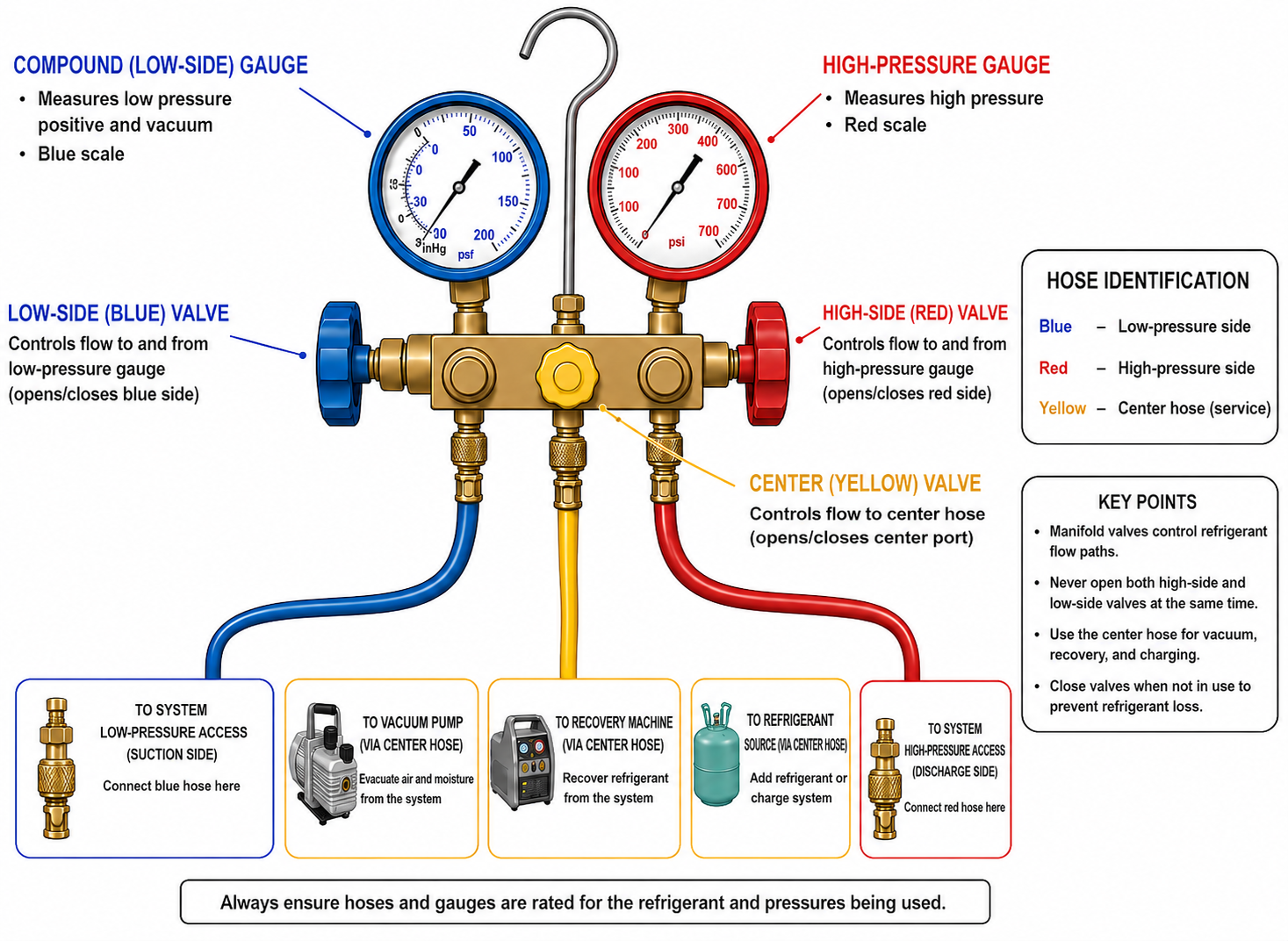
Figure 4.5.1 – Main parts of a traditional two-valve refrigeration manifold gauge set.
AI-generated instructional figure: It may contain visual inaccuracies. Use the accompanying lesson text and cited authoritative sources to verify technical and regulatory details.
Figure 4.5.2
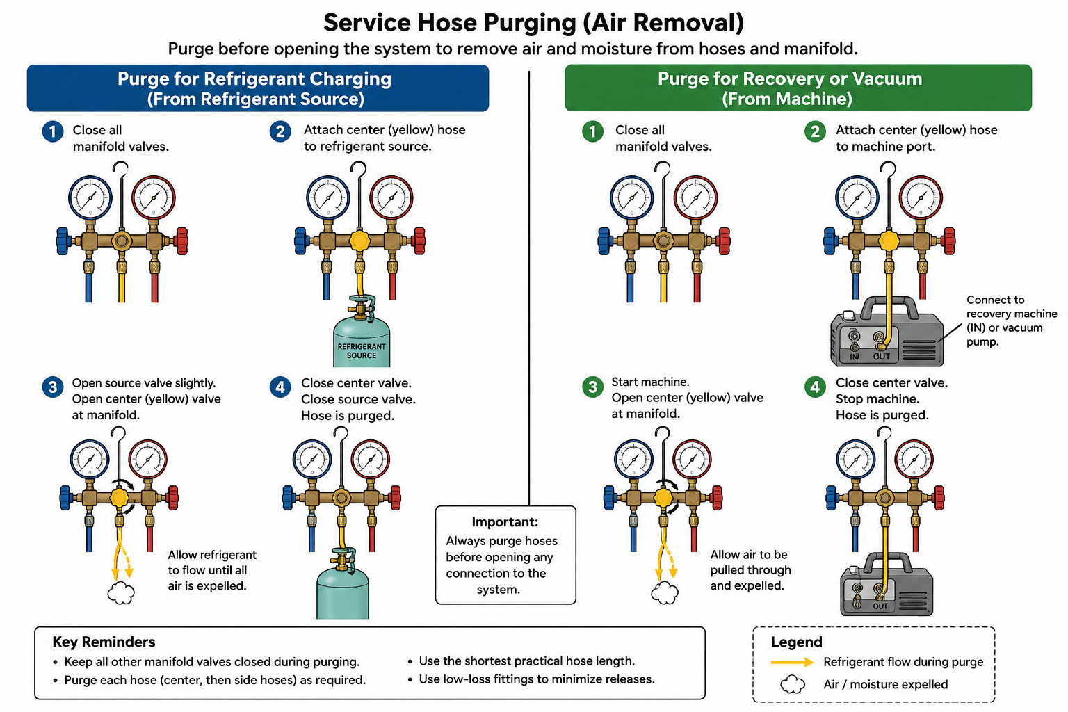
Figure 4.5.2 – Typical manifold service connections for pressure measurement, charging, recovery, and evacuation.
AI-generated instructional figure: It may contain visual inaccuracies. Use the accompanying lesson text and cited authoritative sources to verify technical and regulatory details.
EPA 608 Exam Focus
What Students Must Remember
- The compound gauge:
- Is the low-side gauge.
- Measures positive low-side gauge pressure.
- Indicates vacuum below atmospheric pressure.
- Does not replace a micron gauge for deep evacuation.
- The high-pressure gauge:
- Measures high-side pressure.
- On a typical two-valve manifold:
- Low valve connects low side to center.
- High valve connects high side to center.
- Gauges normally read connected side pressures with manifold valves closed.
- The center service hose can connect to:
- Refrigerant source.
- Recovery machine.
- Vacuum pump.
- Common hose colors are:
- Blue → low side.
- Red → high side.
- Yellow → center service hose.
- Hose color is a convention, not a substitute for tracing and labeling.
- Low-loss fittings reduce refrigerant release during connection/disconnection.
- Low-loss does not mean zero-loss.
- Current federal recovery/recycling-equipment standards require low-loss fittings on covered equipment hoses.
- Connecting and disconnecting hoses can release refrigerant and is a refrigerant-handling activity.
- Air should not be introduced into the sealed refrigeration circuit through service hoses.
- Hose air-removal procedures must minimize refrigerant release.
- Incidental de minimis connection losses do not create general permission to vent.
- A recovery machine has a specific inlet and outlet.
- Refrigerant must be recovered before evacuation of a charged system.
- A vacuum pump removes air and water vapor; it is not the refrigerant recovery machine.
- Manifold and hose pressure ratings must be suitable for the refrigerant/system.
- Residual refrigerant in hoses can cross-contaminate another system.
High-Priority Comparison Table
| Exam Clue | Correct Concept |
|---|---|
| Low-side pressure and rough vacuum | Compound gauge |
| High-side pressure | High-pressure gauge |
| LOW ↔ CENTER | Low-side manifold valve open |
| HIGH ↔ CENTER | High-side manifold valve open |
| External service-device connection | Center port / center hose |
| Charge source connected here | Center hose |
| Recovery-machine inlet connected here in common manifold setup | Center hose |
| Vacuum pump connected here in common manifold setup | Center hose |
| Deep vacuum | Micron gauge, not compound gauge alone |
| Reduce hose disconnect emissions | Low-loss fitting |
| Pressure measurement only | Side hoses connected; center isolated; valves normally closed |
| Air trapped in hose | Remove by approved low-emission procedure before introducing contents into system |
Typical Exam Question Patterns
Students may be asked to:
- Identify which gauge is the compound gauge.
- Identify which gauge reads high-side pressure.
- Identify the purpose of the center manifold port.
- Identify what the low-side manifold valve connects.
- Explain whether manifold valves must be opened to read pressure.
- Select the center-hose device for charging.
- Select the center-hose device for recovery.
- Select the center-hose device for evacuation.
- Explain why air must be removed from service hoses.
- Explain the purpose of low-loss fittings.
- Distinguish incidental connection loss from intentional venting.
- Recognize why a compound gauge cannot verify deep vacuum.
- Identify a reversed recovery-machine connection.
- Recognize the risk of using hoses with inadequate pressure ratings.
Common Mistakes and Confusing Points
Mistake 1: Opening the Manifold Valve Just to Read Pressure
On a typical manifold, gauges normally read their connected side pressures with the manifold valves closed.
Mistake 2: Thinking the Low-Side Valve Turns the Low Gauge On and Off
The valve primarily controls communication between the low-side port and center service port.
Mistake 3: Calling the Center Hose Only a Charging Hose
The center hose can serve charging, recovery, or evacuation depending on the procedure.
Mistake 4: Using the Compound Gauge to Verify a Deep Vacuum
Use a micron gauge for deep-vacuum verification.
Mistake 5: Assuming Hose Color Proves the Connection
Trace the hose and identify the actual port.
Mistake 6: Opening Both Manifold Valves on an Operating System Without a Reason
This can connect the high and low sides through the manifold.
Mistake 7: Purging Air by Routinely Venting Refrigerant
Air must be removed while refrigerant release is minimized. Do not treat deliberate venting as a normal hose-clearing method.
Mistake 8: Reversing Recovery-Machine Inlet and Outlet
Refrigerant flows:
Appliance
→ Recovery-machine inlet
→ Recovery machine
→ Recovery-machine outlet
→ Recovery cylinder
Mistake 9: Treating Low-Loss as Zero-Loss
A low-loss fitting minimizes release; small incidental losses can still occur.
Mistake 10: Ignoring Hose Pressure Rating
The hose must be rated for the actual refrigerant and expected system pressure.
Concept-Check Questions
Question 1
What is the primary purpose of the compound gauge on a traditional manifold gauge set?
A. Measure only high-side discharge pressure
B. Measure low-side positive pressure and indicate vacuum below atmospheric pressure
C. Measure refrigerant mass in the charging cylinder
D. Verify deep vacuum accurately in microns
Question 2
On a typical two-valve manifold with the low-side and high-side hoses connected to an operating system, how are pressures normally read?
A. Both manifold valves must be fully open.
B. Only the high-side valve must be open.
C. The gauges can normally read their connected side pressures with both manifold valves closed.
D. The center hose must be connected to a vacuum pump.
Question 3
What is the main function of the center service port on a traditional manifold gauge set?
A. Provide a common connection for service equipment such as a refrigerant source, recovery machine, or vacuum pump
B. Measure only compressor discharge temperature
C. Permanently connect the high side directly to the low side
D. Replace the low-side access fitting on the appliance
Question 4
In a common manifold-based recovery arrangement, where is the center hose connected?
A. Directly to the recovery-cylinder liquid valve with no recovery machine
B. To the compressor discharge line only
C. To the vacuum-pump exhaust
D. To the recovery-machine inlet, with the recovery-machine outlet connected to the recovery cylinder
Question 5
Why must air be removed from a charging hose before the hose contents are introduced into a sealed refrigeration system?
A. Air can introduce noncondensables and moisture into the system.
B. Air changes every refrigerant into an azeotrope.
C. Air automatically lowers compressor discharge pressure.
D. Air prevents the compound gauge from reading positive pressure.
Question 6
What is the purpose of a low-loss fitting?
A. Increase compressor capacity during charging
B. Convert gauge pressure directly to absolute pressure
C. Minimize refrigerant release when hoses or service equipment are disconnected
D. Remove moisture from refrigerant
Question 7
Which instrument should be used to verify a deep evacuation in the micron range?
A. High-pressure gauge
B. Micron gauge
C. Ordinary compound gauge only
D. Refrigerant cylinder scale
Question 8
Which statement about manifold service hoses is most accurate?
A. Hose color alone proves which refrigerant and pressure rating the hose can safely handle.
B. A hose may be used with any refrigerant if the threaded fitting connects.
C. Refrigerant trapped in hoses cannot cause cross-contamination.
D. Hoses and fittings must be suitable for the refrigerant and pressure, inspected before use, and handled to minimize releases and contamination.
Answers and detailed explanations will be provided in
4.11 - Answers and Explanations.md.
Section Summary
A traditional manifold gauge set combines:
Compound gauge
+
High-pressure gauge
+
Low-side valve
+
High-side valve
+
Low-side hose
+
High-side hose
+
Center service hose
The compound gauge:
Measures low-side positive pressure
+
indicates rough vacuum
The high-pressure gauge:
Measures high-side pressure
On a typical two-valve manifold:
Low valve open
→ LOW ↔ CENTER

High valve open
→ HIGH ↔ CENTER
The gauges normally read their connected system pressures even with the manifold valves closed.
The center hose can connect to:
Refrigerant source
or
Recovery machine
or
Vacuum pump
Good service practice requires the technician to:
- Know the actual low-side and high-side access points.
- Understand manifold valve flow paths.
- Remove air from hoses without routine intentional refrigerant venting.
- Use low-loss fittings.
- Minimize trapped refrigerant release.
- Use pressure-rated and refrigerant-compatible hoses.
- Prevent cross-contamination.
- Use a micron gauge—not the compound gauge alone—to verify deep evacuation.
- Follow recovery-machine and equipment manufacturer connection instructions.
The next section explains gauge pressure, absolute pressure, atmospheric pressure, vacuum, and micron units.
See Section 4.6 - Gauge Pressure Absolute Pressure and Vacuum.
References
Current Regulatory Sources
-
U.S. Environmental Protection Agency, Stationary Refrigeration - Prohibition on Venting Refrigerants, accessed August 8, 2026.
-
U.S. Environmental Protection Agency, Section 608 Technician Certification Requirements, accessed August 8, 2026.
-
U.S. Environmental Protection Agency, Definitions of Section 608 Terms, accessed August 8, 2026.
-
Electronic Code of Federal Regulations, 40 CFR § 82.152 - Definitions, accessed August 8, 2026.
-
Electronic Code of Federal Regulations, 40 CFR § 82.158 - Standards for Recovery and/or Recycling Equipment, accessed August 8, 2026.